Any experience with sandvik corocut MB?

Spruewell

Well-known member
Joined
Mar 6, 2021
Messages
674
Reaction score
441
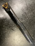
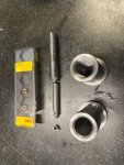
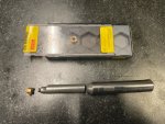
I’m running a job doing a pair of bushings in 12L14 with an internal thread (M20x2.5 and M24x3.0). A rather tight bore and coarse pitch. I was planning on running both parts with the same bar and insert to save some tooling and setup cost. I ended up getting a Sandvik Corocut MB bar and inserts. Nice looking little solid carbide, through coolant bar that was the perfect length to reach the 2” thread depth I needed.
Got the job all set up and started making first articles while dialing in feeds and speeds. As I was fine tuning the threads, I noticed that the adjustments I was making were not holding stable.. the screw holding the insert on the end of the bar had loose up. No problem, torque that thing down a little better and off I go. About 250 parts later, I’m getting smooth bore bushings. The bar snapped off. Ok, order another.
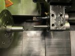
Tool shows up and is installed today. I run a first article, everything looks good. Off to the races! 5 parts later and something doesn’t sound right.
92C2EC81-E47A-4E8A-89A0-5270FA2ECF82.jpeg

1681F25B-590A-4CE6-A30D-DEF7125522AF.jpeg8804620A-7C0D-4F17-A600-B46D06A0DA3B.jpeg

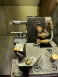
Anyone have a similar experience with these? Am I missing something? At this point I’m going to have to make something else work as I have just about exceeded the budget on this project (them little suckers are pricey)

almost forgot to mention I had it running about 625rpm to keep the chatter down. Started out with .01” doc, then about halfway down backed off to .005” doc with a spring pass at the end.
 
Last edited:

lobust

Moderator
Staff member
Joined
Mar 17, 2021
Messages
926
Reaction score
902
Location
Orkney Islands, UK
I use those a lot, and have never broken one like that. Never had a screw back off either...

I have broken brazed ones from pushing them too hard.

That said, I'd be using a 16mm laydown bar with full profile inserts for both those threads. That's a big thread for that bar.

How is the thread terminated? Are you threading into an undercut or are you pulling out with no undercut? If the latter, it's quite likely that you are overloading the bar at the end of the thread. CNC lathes IME are not really capable of maintaining a perfectly uniform chipload in the runout of a thread, and you're already pushing the envelope on the load on that tool...

If you are threading into an undercut, then most likely you are simply overloading the bar as the insert gets dull.
 

Jashley73

Well-known member
Joined
Mar 29, 2021
Messages
398
Reaction score
401
Location
Louisville, Kentucky
Those are coarse threads for sure. I'm not sure what infeed strategy you were using - maybe an alternating-flank, or some kind of variable depth infeed strategy would help keep the cutting load down on the tool. That might help explain the broken shank. Maybe...

I'm also curious of your infeed angle as well. For an internal thread, on a conventional infeed strategy - you'd want to be Z-negative/X-positive for each infeed. Ideally, this would keep the feed forces pushing the insert into the shank. If for some reason that infeed was reversed - Z-positive for example - then you would be trying to pull the insert off the shank, and I could see that upsetting the screw. So in that case, maybe alternating-flank infeed would NOT be the way to go...


I will say, your setup looks pretty solid though. I'd get in touch with Sandvik, and see if they'll replace your shank for you. They might even have some fancy thread-infeed calculating software just for these situations.
 

Mr. Atoz

Active member
Joined
Apr 29, 2021
Messages
156
Reaction score
149
Are you running these from long bar stock, or cutting individual pieces?
 

Spruewell

Well-known member
Joined
Mar 6, 2021
Messages
674
Reaction score
441
Right now, the infeed is straight. I'm using G92 going into a blind hole. It's running out 68 pieces out of a 12' bar. I start with a through coolant insert drill to blow the hole into the material about 1/4" past the part length, followed by the boring bar to finish and control the bore size. After that the threading bar goes in. I also use the threading bar to produce the champfer at the end of the thread and make a clean part off with minimal burr. I've been looking around for an alternative bar with R166 type laydown inserts, however, all that I have been finding to go into that bore diameter are coming up with a number 11 size (1/4" inscribed circle). I have not found any that can reach the thread depth.
 

Spruewell

Well-known member
Joined
Mar 6, 2021
Messages
674
Reaction score
441
Alternating flank infeed sounds interesting. However, I have a FANUC 0T control on this machine and I don't think that is an option.

The code I'm running is:

N3
T0303M28
G00 G99 G97 X0.665 S650 M93
Z0.2
G92 X0.68 Z-2.01 R-.0005 F.0984
X0.7
X0.72
X0.74
X0.75
X0.76
X0.765
X0.77
X0.775
X0.78
X0.785
X0.79
X0.795
X0.793
G00 Z.5
M1
N23 (CHAMFER CYCLE)
T0303 M28
G00 G96 X0.65 S300 M93
Z.01
Z-1.93
G01 X0.802 Z-2.015 F.001
X0.75
G00 C.65
X-0.112
G01 X0.815Z-0.04
Z0.01F.004
G00 Z1.
M1

And just in case you were wondering, Tool length is set to the end face of the tool, not the thread point so where it appears to cut into the part as it exits is really just cleaning up the champfer made by the boring bar ahead of it
 

Spruewell

Well-known member
Joined
Mar 6, 2021
Messages
674
Reaction score
441
I ended up modifying a R166.4KF-D10 5/8 shank threading bar to fit in there.

E1BA537D-A355-493C-9C4B-943D39C8DE3A.jpegA1BEAF2F-14C2-43A2-9746-3A3CB19D5004.jpeg

I ran out of X travel so I had to turn it around to thread on the negative side.

I did not beat the tool block to death. I got the machine used and the previous operator was a little heavy handed
 

Jashley73

Well-known member
Joined
Mar 29, 2021
Messages
398
Reaction score
401
Location
Louisville, Kentucky
Man, straight infeed is going to put a lot of extra tool pressure on whatever tool that you're using. I'd try infeeding on a 29-30° infeed angle, and see if that helps.

Straight infeed 0° infeed, or X-axis only, more than doubles tool pressure. You now have two faces under cutting pressure, but the rub is that the tip is bearing the force of two different chip formations colliding right at the weakest point of the tool.

My guess is that switching to a 29-30° infeed angle would resolve those issues.
 
Last edited:

Mr. Atoz

Active member
Joined
Apr 29, 2021
Messages
156
Reaction score
149
Odd that 12L14 is giving you so many problems. Perhaps your chips are not always evacuating your bore.
 

Spruewell

Well-known member
Joined
Mar 6, 2021
Messages
674
Reaction score
441
Well. I had it all set and just got it running. Got a phone call from a customer and when I came back I could see the glow from the indexable drill as it tried to continue on without the inserts. Unfortunately the phone call lasted long enough for it to have wiped out the boring bar and the threading bar. I think I need to go to the bar and get wiped out now too. I was too upset to take pictures. Got on the phone with the tool supplier only to find that Sandvik no longer makes the R166.4 style U-lock threading bars for the 3/8 IC (R166.0 16) inserts . I’m looking for alternatives.
 

lobust

Moderator
Staff member
Joined
Mar 17, 2021
Messages
926
Reaction score
902
Location
Orkney Islands, UK
Do you already have a bunch of 166 style inserts? They are unfortunately not forward compatible with the 266 tools, although the 266 inserts are backwards compatible with the 166 tools.

In your shoes, my approach would be to find a bar on ebay and use it until your stock of 166 inserts is depleted, then switch to 266. Going from Sandvik to any other threading system is a significant downgrade.

I also advise you not to ignore Jashley's advice about infeed angle. I almost never use straight infeed. Sometimes it can help with chip formation in certain materials, but generally it just creates more tool load and promotes chatter. Alternate flank infeed is generally the best infeed method, but not all controls offer that as a cycle and doing it longhand isn't much fun. On my dumb Fanucs I use G76 and 55deg thread angle for 60deg threads. That is a 27.5deg infeed angle, which still creates more tool pressure than a 30deg infeed angle but leaves a better finish on the trailing flank of the thread.
 

Spruewell

Well-known member
Joined
Mar 6, 2021
Messages
674
Reaction score
441
I was reading up on it in the manual. The G76 cycle looks like the ticket. I don't know why I hadn't used it before. G32 sucks to program, or at least the example in the manual makes it look lengthy and cumbersome. And it doesn't appear to have any advantage over G92 other than requiring a huge amount of extra programing for the same result.
 

Spruewell

Well-known member
Joined
Mar 6, 2021
Messages
674
Reaction score
441
Having some trouble with the G76 cycle. The example in the book is as follows:

N001 T0500
N002 G97 S610 M03
N003 G0 X3.0 Z3.425 T0505 M23
N004 G76 P010560 Q.005 R.005
N005 G76 X2.19 Z1.0 P0.155 Q .05 F.25
N006 G0 X3.5 Z1.0 M24
N007 G0 X0 Z0 T0000
N008 M01

my control won’t allow a ”P” command with a decimal point as it shows on line N005. And I keep getting a 007 alarm.
 

Vancbiker

Administrator
Staff member
Joined
Mar 21, 2021
Messages
1,630
Reaction score
1,674
Location
Vancouver, Washington. USA
What book? My Fanuc books do not show P with a decimal point though the examples are different.

P in the second G76 line is height of the thread on a side (radial amount) and no decimal allowed with the address P
 

lobust

Moderator
Staff member
Joined
Mar 17, 2021
Messages
926
Reaction score
902
Location
Orkney Islands, UK
IME Fanuc controls are a bit schizophrenic about decimal points in G76. Some accept it, some don't, some seem to be able to take either and somehow figure it out.

I have four fanuc lathes, 0-TC, Oi-TD, 21-T, 31ib5 and use G76 on all of them, but there is not much coherency on the decimal point thing between them
 

Spruewell

Well-known member
Joined
Mar 6, 2021
Messages
674
Reaction score
441
Turns out the example in the book does not work. I did get it working.

T0303 M28
G0 G97 X.675 S1000 M93
Z.2
G76 P020355 Q050 R.005
G76 X.804 Z-2.1 R-.0015 P0500 Q060 F.0984
G0 X.5
M1

I’m a little confused however. The book goes into a lot of detail about how to calculate the number and subsequent depths of cut, but the G76 cycle doesn’t seem to give you very much control over that.
 

lobust

Moderator
Staff member
Joined
Mar 17, 2021
Messages
926
Reaction score
902
Location
Orkney Islands, UK
Turns out the example in the book does not work. I did get it working.

T0303 M28
G0 G97 X.675 S1000 M93
Z.2
G76 P020355 Q050 R.005
G76 X.804 Z-2.1 R-.0015 P0500 Q060 F.0984
G0 X.5
M1

I’m a little confused however. The book goes into a lot of detail about how to calculate the number and subsequent depths of cut, but the G76 cycle doesn’t seem to give you very much control over that.
Fanuc's threading cycles suck pretty hard, that's old news! Bill told me years ago about the single line version of G76 that at least allows alternate flank infeed, but I've yet to get around to trying it.

You have a fairly good amount of control over chipload in G76, just no absolute control over the number or depth of passes.

In the first line, Q defines the depth of the first pass. R defines the depth of the last pass.
In the second line, Q defines the depth of the second pass.

The cycle perfoms the first pass at Q1, then uses Q2 and R1 to do it's black box calculations about the diminishing DOC's of the remaining passes, until it is R1 away from final depth. AFAIK Fanuc have never published any information about how G76 actually calculates each pass.

Note that R in the second line defines a taper thread, idk if you did that intentionally or not...
 
Top Bottom