CNC Machining Helical Oil Grooves

machinery_e

New member
Joined
Feb 13, 2021
Messages
23
Reaction score
18
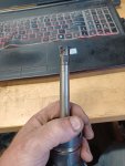
I'm working on machining figure 8 oil grooves in bronze bearings, using a manual lathe. 3.5" ID, 4" lead, 1/8" grooves. Grooves have specific start/stop points. (In other words, the grooves have to be captive in the bushing, the grooves can not lead in/out.) Lathe's slowest speed is 11 RPM. Needless to say with all that, its a very challenging job.

Running them on a CNC lathe is pretty much out, but would love to hear some of the methods used on a CNC lathe. Curious how you handle the right hand/left hand grooves? Is there a special tool that allows you to machine both at once? Or are two grooving bars used, one left hand, one right hand?

I have an idea tool wise for machining them on a CNC mill with rigid tapping which I do have access to. Programming is the tricky part-not sure its possible. With the length of the bushings (4.5") a tool to cut the 1/8" grooves, like a lollipop cutter, I think would have way too long of a length to diameter to ratio to use a conventional G2/G3 helical interpolation cycle. With my tool ideal, it would be would be perfect if the G2/G3 cycle could be combined with the rigid tapping cycle-is that even possible???

Thanks so much!
 

lobust

Moderator
Staff member
Joined
Mar 17, 2021
Messages
926
Reaction score
903
Location
Orkney Islands, UK
Real difficult to do on a manual, it's hard to get a low enough ratio for screwcutting, most lathes are not able without special gearing.

I do it fairly frequently on a cnc lathe using the C axis and a full radius grooving tool using a simple macro that I wrote. It's more like broaching than screwcutting because the helix angle is so steep. Most of the ones I do are captive grooves - as in they don't extend to the ends of the bearing, which really rules out screwcutting. If you don't have that restriction, simple screwcutting on a CNC lathe will happily get the job done with a low enough rpm. You can use the same tool, just cutting in opposite z direction. Difficult to get the grooves timed to each other doing it that way though. Again, much easier with C axis.

The problem with rigid tapping for this kind of application is that the tool has to retract along the same path. No way to offset it short of some mechanical means. For most tools dragging them backwards doesn't go too well...
 

Doug

Well-known member
Joined
Mar 2, 2021
Messages
1,169
Reaction score
789
Location
NW pa.
Have you tried a die grinder with a ball shaped burr, mounted in the tool post ?

By the way, there used to be a specific machine called , IIRC a Wicaco oil groover, made for the job, looked like a Mitts & Merrill keyway broach
machine.
 

Herding Cats

Hardplates
Joined
Feb 1, 2021
Messages
2,235
Reaction score
1,999
Location
Primary: State of Confusion Secondary: PA
Website
speartoolandmachine.com
I'm a mill guy so no need for me to fool around wasting time when it's a simple job for me to do on a mill.

In the past I've used both lollipop mills as well as radius-ed key cutters.

Due to the nature of oil/grease grooves the tolerance is usually pretty loose so when using a radius-ed key cutter the extra material removed due to the steep lead angle usually isn't an issue.

Iscar as well as others have those multi master type things that the cutter threads or bolts on to a carbide shank for long reaches.


Getting the right tip for one of these things should easily get you where you want to go.

20210822_084523.jpg
 

Vancbiker

Administrator
Staff member
Joined
Mar 21, 2021
Messages
1,632
Reaction score
1,677
Location
Vancouver, Washington. USA
I did similar on large (~4” id by 6” long) bushings years ago on a 2 axis CNC lathe using G0. Used a hand ground HSS tool. Made the start groove and end groove. Then figured out how many RPM it took to get one rev at 400IPM in a 5.5” length. Figured out a tiny dwell at the bottom to get the groove roughly 180 off and then rapid back to the start groove. Finish bore then a few swipes with a wire brush with CW and CCW spindle to knock off any burrs.

The place that used to make them used a modified engine lathe with a 90 degree head die grinder on the tool post. They had changed gearing on the lead screw to speed it up relative to the spindle which had been geared down to really slow, like <1 RPM. They had made 2 piece barrel cams that clamped over the lead screw. A lever mounted cam follower was mounted to the carriage. The operator would position the cam follower in the start groove the feed the cross slide to depth. That cut the start groove. Then he applied pressure to the carriage so the follower would slide into the helix of the barrel cam. When the carriage reached the end of the cam the operator let is sit there for a rev to cut the end groove. Then he applied pressure to the carriage to start the follower into the return helix of the cam. Kind of Rube Goldberg, but other than being pretty slow, worked well.
 

g-coder05

Administrator
Staff member
Joined
Feb 8, 2021
Messages
687
Reaction score
529
Location
Capones Island Philippines
Website
machinistboard.com
the way I’ve always cut those grease gullies in Die Post Bushing before I had CNC was a manual driven dividing head with an HSS ground toolbit sticking out of a horizontal arm. Basically running it like a shaper.

696BE5BB-EC48-401E-8188-C3653C21F63E.jpeg
 

Carbidebob

Member
Joined
Jun 19, 2021
Messages
62
Reaction score
62
Age
66
Running them on a CNC lathe is pretty much out,
So now we get into real work.
This basically real high lead threads.
In most a reverse thread or groove.
This cut will not like a normal thread or grooving as you will run out of heel clear real fast.
Small land and big secondary.
 

Spruewell

Well-known member
Joined
Mar 6, 2021
Messages
674
Reaction score
441
a lathe with live milling would do this with no trouble using a radiused key cutter or lollipop cutter. Or a 4th axis tilted up on its back In a VMC
 

lobust

Moderator
Staff member
Joined
Mar 17, 2021
Messages
926
Reaction score
903
Location
Orkney Islands, UK
a lathe with live milling would do this with no trouble using a radiused key cutter or lollipop cutter. Or a 4th axis tilted up on its back In a VMC
If you're already on a live tool lathe, my method works much better. The problem with using a rotary tool of any description for this is you make grooves that are WAY too wide.

Here is the rough and ready macro - I wrote it in a hurry years ago and we've just been using it as is ever since.

%
O9017(HELICAL BROACHING)

(X FINAL DIAMETER)
(Z Z END POINT)
(H INCREMENTAL ROTARY DISTANCE)
(F TANGENTIAL FEED RATE)
(Q DEPTH OF CUT)
(D SPRING PASSES)

#550=#5001(INITIAL X)
#551=#5002(INITIAL Z)
#552=#5005(INITIAL C)
#553=#550

WHILE[#553LT#24]DO1
G01Z#26H#11F#9
G00X[#550-[#18*2]]
Z#551C#552
#553=[#553+[#17*2]]
IF[#553GT#24]THEN#553=#24
X#553
END1

#554=-1
WHILE[#554LT#7]DO1
G01Z#26H#11F#9
G00X[#550-[#18*2]]
Z#551C#552
X#553
#554=#554+1
END1
M99
%

And this is the tool that I use:

IMG_0406.JPG

It creates a really nice sharp semi-circular profile helical groove - unfortunately I don't have any parts on hand to take a picture of, so you'll just have to take my word for it 🙂
 

angelw

Well-known member
Joined
Mar 21, 2021
Messages
313
Reaction score
595
It can be done with a two axis lathe without a "C" axis, with the Continuous Threading Function using G32. The tool can be fed to the required DOC using G32; accordingly, the groove can be started in from the end of the work-piece. If numerous passes are required to get to full depth, a simple DO LOOP can be used to repeat the tool path until full depth is reached.

Regards,

Bill
 

lobust

Moderator
Staff member
Joined
Mar 17, 2021
Messages
926
Reaction score
903
Location
Orkney Islands, UK
It can be done with a two axis lathe without a "C" axis, with the Continuous Threading Function using G32. The tool can be fed to the required DOC using G32; accordingly, the groove can be started in from the end of the work-piece. If numerous passes are required to get to full depth, a simple DO LOOP can be used to repeat the tool path until full depth is reached.

Regards,

Bill
What I originally found, and the reason I went with the method above, is that at the very low speed required to do this the spindle would not reliably maintain it's speed when the cut started - it would bog down and then catch up, which led to gouging and when the tool was fully engaged, stalls and broken tools. On a bigger lathe with a geared spindle it probably would be a non issue, but on my direct drive machine using C/Z interpolation was the solution and we've been doing it that way since.
 

angelw

Well-known member
Joined
Mar 21, 2021
Messages
313
Reaction score
595
What I originally found, and the reason I went with the method above, is that at the very low speed required to do this the spindle would not reliably maintain it's speed when the cut started - it would bog down and then catch up, which led to gouging and when the tool was fully engaged, stalls and broken tools. On a bigger lathe with a geared spindle it probably would be a non issue, but on my direct drive machine using C/Z interpolation was the solution and we've been doing it that way since.
Largely dependent on the type of material being used, it may be required that quite small DOC be used, but if all that is available is a two axis lathe without a "C" axis, there is not much choice. With Continues Threading, the initial engagement with the work-piece can occur gradually over a relative long distance by specifying X and Z in the same G32 Block. This gradual feed into depth can be repeated until Full Depth is reached, then an additional pass at depth to clean up the ramp in cut section of the tool path is made. To exit the tool path, another X/Z move under G32 control to be clear of the work in X is made.

Regards,

Bill
 

g-coder05

Administrator
Staff member
Joined
Feb 8, 2021
Messages
687
Reaction score
529
Location
Capones Island Philippines
Website
machinistboard.com
What I originally found, and the reason I went with the method above, is that at the very low speed required to do this the spindle would not reliably maintain it's speed when the cut started - it would bog down and then catch up, which led to gouging and when the tool was fully engaged, stalls and broken tools. On a bigger lathe with a geared spindle it probably would be a non issue, but on my direct drive machine using C/Z interpolation was the solution and we've been doing it that way since.

I used to do a lot of self reversing shafts and ran into this exact problem. On steep pitches with slow RPM's the spindle acted like it had lash in it. If you looked real close it seamed to stall then catch back up with itself. The thread pitch was right but the finish looked like it was formed with a chisel.
 

Vancbiker

Administrator
Staff member
Joined
Mar 21, 2021
Messages
1,632
Reaction score
1,677
Location
Vancouver, Washington. USA
When I was doing the grease grooves the machine had a 2000C control. A thread cycle would not work because the lead was limited to .999999” and I needed a 5.5” lead.
 

angelw

Well-known member
Joined
Mar 21, 2021
Messages
313
Reaction score
595
I used to do a lot of self reversing shafts and ran into this exact problem. On steep pitches with slow RPM's the spindle acted like it had lash in it. If you looked real close it seamed to stall then catch back up with itself. The thread pitch was right but the finish looked like it was formed with a chisel.
The issue is a change in the spindle speed, as indicated in Gregor's Post #14. If a different spindle speed is programmed during the repeat of the Threading Passes, a new Thread Start will be produced. When the machine is low in torque, with a direct drive and low spindle speed, although another spindle speed is not specifically programmed, the result is the same if the spindle should slow through load being applied via the tool.

I've cut many figure 8 oil grooves using Continuous Threading G32 and provided you don't get too aggressive with the DOC, it works fine.

Regards,

Bill

When
 

Vancbiker

Administrator
Staff member
Joined
Mar 21, 2021
Messages
1,632
Reaction score
1,677
Location
Vancouver, Washington. USA
I wonder if it would have been possible in metric?
AFAIK, that would have required a different machine. Imperial/metric switching was not a feature on that control. The lead address was E and allowed 6 places past the decimal to accommodate the odd values of imperial pitches. The machine also used inch pitch screws (.200 on X IIRC).
 
Top Bottom