Electromagnetic spindle brake question or two

alphonso

Well-known member
Joined
Apr 28, 2021
Messages
554
Reaction score
316
Location
98 05'14.42" W 31 05' 08078" N
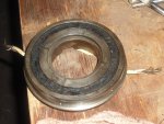
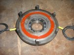
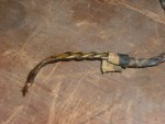
Italian built lathe, same one as thread below. Uses an electromagnetic brake to stop the spindle. Assembly is buried inside the headstock(at the bottom). After finally figuring out the butchered wiring, I got the brake to function. Worked well for about a week. However, it has started blowing fuses after a short period of time.

I asked the company in Italy what the amp draw should be and they said 1.8 amps. Put the ammeter on it and it is drawing 8 amps and after 10 minutes it blows a 15 amp fuse.

Company says they can get me an assembly for 1100 euros in a week's time.

I wonder, can the electro-magnet be rewound? For less than 1100 euros? What is the exchange rate this week?
 

Mud

Well-known member
Joined
Feb 12, 2021
Messages
2,151
Reaction score
2,107
Location
South Central PA
They are usually potted, I suspect rewinding would be tough.
Can you get a good look at the brake, even take a photo of it? I ask, because I found the axis brake for my Deckel FP7NC from the OEM rather than from the machine manufacturer at about half price and 1 week instead of 8 by looking through google images. I can't find the name ATM, but it was a european company I'd never heard of (not German), and the brake was an odd configuration that no other manufacturer made so I couldn't easily substitute another. I googled electromechanical brake images and on about page 4 I saw a picture of a brake very much like mine, and pursued links until I found the company. Not quite that quick, but that was the successful process. You might not have such a hard time, you might be able to match yours up from it's dimensions and catalog pages.
 

Machtool

Well-known member
Joined
Mar 20, 2021
Messages
197
Reaction score
336
Location
Melbourne Australia.
They are usually potted, I suspect rewinding would be tough.
Fairly certain O.E.M's dont make their own brakes. Otlieb Ortlinghaus, Stromag, Warner, Binder, Matrix etc.
I have these blokes 60 yards across the road from me. Melbourne Electric Moter rewinders, They will cut open a brake or clutch coil.
Work out how many turns, bonus points if I know voltage & current. Then they do that Ohms law thing and resistance drop per metre, via wire diameter. I've had them rewind a few clutches and brakes. But they are old school Europeans. There's no better place to have an Expresso at 9,00 in the morning, loaded with Galianno.
I'm starting to think, that's becoming one of the lost arts.

As always. Phil.
 
Last edited:
  • Like
Reactions: Mud

alphonso

Well-known member
Joined
Apr 28, 2021
Messages
554
Reaction score
316
Location
98 05'14.42" W 31 05' 08078" N
Details.

Machine is a Lansing G40. -- 40"X240" flat bed engine lathe. Imported from Italy by S&S Machinery in New York. S&S defunct about 2012. Machine has many similarities with Gornati machines. That is the company that I have been dealing with.

The brake coil is internal to, at the bottom of the headstock From drawing, it appears to be removable from the front. Don't know if it is in the sump. Can not be seen from above with top off.

Brake operates on 28VDC. 1.8 ohms between wires. 1.1 ohms to ground. Expected that to be open.

1624540048101.png

This is a brake shown on the Gornati site. May or may not be similar to what is in my machine. Drawing labels it as SR 10 AC. Gornati quoted E-10. ????????? Device is probably about 6 inchs diameter.

I can run the lathe without the brake. I guess I'll do that until i finish the job that is in it.
 

Vancbiker

Administrator
Staff member
Joined
Mar 21, 2021
Messages
1,630
Reaction score
1,674
Location
Vancouver, Washington. USA
........1.1 ohms to ground. Expected that to be open..........
Yes, that 1.1 to ground is bad. I have seen brake coil wires chafe through insulation right where the wire enters the body of the coil. Also seen them break there. First thing I’d check is chafed/cracked insulation there.

As Phil mentioned previously, most old school motor repair shops could rebuild the coil
 

lobust

Moderator
Staff member
Joined
Mar 17, 2021
Messages
926
Reaction score
902
Location
Orkney Islands, UK
Machine has many similarities with Gornati machines.
Is this the lathe you were doing the electrical work to in your other thread?

If it's the same as the Gornati's it will be well worth the time to fix up, dad has a Gornati Legoor (350 from memory) and it's a really nicely built machine. One of the better centre lathes I have seen for sure.
 

Herding Cats

Hardplates
Joined
Feb 1, 2021
Messages
2,235
Reaction score
1,999
Location
Primary: State of Confusion Secondary: PA
Website
speartoolandmachine.com
For it to draw 1.8 amps at 28vdc I would expect the coil resistance to be around 15-16ohms. If you can ID and repair the short(s) to the case maybe it will increase.

There was a mention of potting. If it is potted, potted components are usually extremely mechanically robust. Being there are no IC's and such components inside that could fail, the odds are in your favor that everything inside the potting is ok......maybe
 
Last edited:

Vancbiker

Administrator
Staff member
Joined
Mar 21, 2021
Messages
1,630
Reaction score
1,674
Location
Vancouver, Washington. USA
For it to draw 1.8 amps at 28vdc I would expect the coil resistance to be around 15-16ohms. ......
Not usually true for a coil where a magnetic core (the brake plate(not a magnet but made of a magnetic material)) exists. Electrical reluctance comes into play due to the change in magnetic flux that occurs when the plate contacts the coil body when the coil is energized.

It’s an interesting phenomena that can be tested with the coil from a DC solenoid valve. Remove the coil from the valve and energize it at the rated DC voltage with an ammeter in circuit. Watch the change in current when you place a steel object in the opening of the coil. It will drop considerably.

Don’t do this exercise too long without a core in the coil. Some coils will draw enough excess current that they will burn up.
 

Herding Cats

Hardplates
Joined
Feb 1, 2021
Messages
2,235
Reaction score
1,999
Location
Primary: State of Confusion Secondary: PA
Website
speartoolandmachine.com
Not usually true for a coil where a magnetic core (the brake plate(not a magnet but made of a magnetic material)) exists. Electrical reluctance comes into play due to the change in magnetic flux that occurs when the plate contacts the coil body when the coil is energized.

It’s an interesting phenomena that can be tested with the coil from a DC solenoid valve. Remove the coil from the valve and energize it at the rated DC voltage with an ammeter in circuit. Watch the change in current when you place a steel object in the opening of the coil. It will drop considerably.

Don’t do this exercise too long without a core in the coil. Some coils will draw enough excess current that they will burn up.
Interesting, I thought the math only got goofy with AC, inductance and so on.

Next time I run over to my storage containers I'll have to grab a solenoid and hook it up to a power supply and play around with it.
 

alphonso

Well-known member
Joined
Apr 28, 2021
Messages
554
Reaction score
316
Location
98 05'14.42" W 31 05' 08078" N
Kevin,
Can only follow the wires about 10 inches down the headstock. I'm afraid I will have to remove the brake before I can really see what's what.

Gregor,
Yes, this the same lathe. Also had a thread about it on PM in the transformers, etc. sub forum. I haven't asked Gornati if they built this machine, yet. The guy I have been dealing with does seem to be real familiar with it.

Doug,

No voltage to coil after fuse blows. Also has switch to disable the brake.
 

Doug

Well-known member
Joined
Mar 2, 2021
Messages
1,168
Reaction score
788
Location
NW pa.
Not sure what you are attempting to communicate. Voltage, amp, or ohms? Take reading where?

On/off switch interrupts the minus side of circuit.
I specified "Voltage".....
and I also said "going to the brake" so go trace out the wiring as far as you can away from the supply, closest to the brake.
There might be other components in series with the brake.
 

Vancbiker

Administrator
Staff member
Joined
Mar 21, 2021
Messages
1,630
Reaction score
1,674
Location
Vancouver, Washington. USA
Interesting, I thought the math only got goofy with AC, inductance and so on.

Next time I run over to my storage containers I'll have to grab a solenoid and hook it up to a power supply and play around with it.
I learned the hard way just how much current flow can change in a coil with no core when trying to get a hydraulic toolchanger resequenced. Slipped all the coils off a bank of solenoid valves so I could override them without fighting the controls attempt to power them. After just a couple minutes I smell hot plastic and see goo bubbling out of a couple coils. After getting the resequence done and getting a couple coils on order, I had a play around with the ammeter and basically did the experiment I outlined in the previous post.
 

alphonso

Well-known member
Joined
Apr 28, 2021
Messages
554
Reaction score
316
Location
98 05'14.42" W 31 05' 08078" N
I specified "Voltage".....
and I also said "going to the brake" so go trace out the wiring as far as you can away from the supply, closest to the brake.
There might be other components in series with the brake.
Hey, I only have one functioning brain cell and it is easily confused.

28vdc going to fuse. 28vdc out of fuse with wires disconnected from brake coil/magnet. This is inside main panel.

Won't get into control station until current job is finished or something goes awry enough to shut me down. Maybe this weekend.

I strongly suspect that the problem will be at or with the brake coil/magnet, not in the wiring to it, with the possible exception of the 2 wires inside the headstock.
 

alphonso

Well-known member
Joined
Apr 28, 2021
Messages
554
Reaction score
316
Location
98 05'14.42" W 31 05' 08078" N
Coil received from Eurton today at lunch time.
DSCF1154.JPG Looks a bit better now.

Question: wires from coil to terminal block are twisted/braided. Is this necessary?
DSCF1152.JPG Gonna replace them anyway, just wondering if the new wires should be twisted like old ones.
 

Vancbiker

Administrator
Staff member
Joined
Mar 21, 2021
Messages
1,630
Reaction score
1,674
Location
Vancouver, Washington. USA
Technically, having the wires twisted reduces the amount of radiated electrical noise. It may help if those wires are run close to say an encoder cable. It won’t hurt and is easy enough to do. A fairly tight twist (turns/inch) and consistent rate provides best effect.
 
Top Bottom