Mcam roughing strategy for this feature?

Freedommachine

Active member
Joined
Jun 7, 2022
Messages
219
Reaction score
249
Location
NE Ohio
I know it's simple but I'm trying to learn something new here. I would usually use a simple 2D contour and multiple roughing passes.

I thought it would be a good candidate for area roughing but I cannot get the right combination of drive surfaces to make it happen. It keeps trying to rough out the slot in the center even though I put a "from outside" containment boundary around it. What am I doing wrong?

It is the top horseshoe shaped feature that I would like to rough out 20230504_140004.jpg
 

Barbter

Well-known member
Joined
May 28, 2022
Messages
777
Reaction score
560
Location
On Tour....
Just taking the centre out - yes?
Or are you talking the whole upper "horseshoe"?

If the whole upper - have you optirough as an available 3D path?
If so, use that as 1st choice.

If just the centre - simply, you could use peel mill.
I'm not in front of mcam now....and I can't remember if you can just chain the "U" and do it (selecting stepover, arc rad, and stock to leave), or draw a central line in the middle of the feature, then use peel mill picking the line, entering the width you want selecting stock to leave etc?

Either way, trochoidal motion is good for these types of shapes and always my first choice.

For finishing, 2D contour spiral ramping down to finish depth and a pocket toolpath standing off the sidewalls 1mm was always my go-to finish paths.
 

Freedommachine

Active member
Joined
Jun 7, 2022
Messages
219
Reaction score
249
Location
NE Ohio
It's still a block of aluminum so I need to remove everything that isn't the horseshoe feature. I tried the dynamic optirough but I got the same results. It will create a nice ramping toolpath to rough out the center of the horseshoe shape but I cannot get it to rough the outside.
 

Freedommachine

Active member
Joined
Jun 7, 2022
Messages
219
Reaction score
249
Location
NE Ohio
Never used M-cam but it looks like you got some type of feature in front of the opening to the pocket. May need to set the lower level at the face or patch the hole with a surface. Or maybe select some chain edges as open edges. Like I said, never used master cam.
That's just a line I put there in an attempt to create a closed boundary chain. I was hoping it would force the toolpath out of that pocket but it did not work.

I'd if it matters or not but for scale; the rough stock is 1.5" x 1.75" x 3.75" aluminum. I had selected a 1/2" 2 flute end mill to rough it out.
 

Herding Cats

Hardplates
Joined
Feb 1, 2021
Messages
2,233
Reaction score
1,993
Location
Primary: State of Confusion Secondary: PA
Website
speartoolandmachine.com
That's just a line I put there in an attempt to create a closed boundary chain. I was hoping it would force the toolpath out of that pocket but it did not work.

I'd if it matters or not but for scale; the rough stock is 1.5" x 1.75" x 3.75" aluminum. I had selected a 1/2" 2 flute end mill to rough it out.
But it appears the pocket floor is deeper or all the way though. A 2d toolpath could easily get confused by that. I'd try patching it off at the floor level and see if it machines the inside and out side.
 

dsj

Member
Joined
Apr 29, 2021
Messages
92
Reaction score
81
Location
Washington
If you're trying the dynamic optirough or any of their dynamic toolpaths, try using avoidance geometry instead of containment. Always worked for me when doing similar things.
 

Barbter

Well-known member
Joined
May 28, 2022
Messages
777
Reaction score
560
Location
On Tour....
Depending upon the version you're running....optirough did change behavior but I can't remember now at what version number.
Draw a rectangle over the part encompassing your stock plus cutter rad, and use that as your boundary. Then tick the box that says "from outside"?
Also you can create a stock model from your stock as OP1.
Then select in the optirough menu your OP1 as stock. This is a more efficient way to go.
If you email me the version number and a step model of your part and cutter size you want to use I'll put something together tomorrow for you.
Metric 🤔 of course?
🥴
 

Freedommachine

Active member
Joined
Jun 7, 2022
Messages
219
Reaction score
249
Location
NE Ohio
Depending upon the version you're running....optirough did change behavior but I can't remember now at what version number.
Draw a rectangle over the part encompassing your stock plus cutter rad, and use that as your boundary. Then tick the box that says "from outside"?
Also you can create a stock model from your stock as OP1.
Then select in the optirough menu your OP1 as stock. This is a more efficient way to go.
If you email me the version number and a step model of your part and cutter size you want to use I'll put something together tomorrow for you.
Metric 🤔 of course?
🥴
That would be very helpful, thank you! I am running Mcam X9. I will send it over in the morning, Ohio time.

I knew there had to be a way to make it recognize the stock when generating toolpaths, only I have no idea how to do it. Mcam YouTube videos are about useless in my opinion.

Solidworks and Mcam constitute the biggest time suck in business for me. I know what I'm trying to make, the damn computer just refuses to listen! 🙄

Freedom Machine is gonna want it in freedom units :cool:
If it ain't some derivative of the king's foot, I don't want it! 🤣

The part does have some metric holes though.

The biggest advantage for me will be seeing how it's done. I have never actually seen an Mcam file from someone else; let alone someone who actually knows how to use the software as it was designed so that will be helpful for sure.

I get what I need from it in the end, but it's usually in a roundabout way that takes 5x longer than it should when I'm dealing with models.

One more question for everyone:
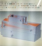
Do you leave edge breaks off of models when you import them into cam software?

As you can see in the pic, I did not suppress them in SW before importing the model to Mcam. The extra surfaces and wireframe it creates seems to add more unnecessary work when chaining; especially since the chamfers can be added in Mcam using a simple '2D chamfer' contour tool path.
 

Barbter

Well-known member
Joined
May 28, 2022
Messages
777
Reaction score
560
Location
On Tour....
I always import 100%, chamfer's wort's, and all!
Because when I finish 'grammin the part, I can run "verify compare to model" and then if I have missed anything, it will highlight in red.
If all is good, the whole verify will be green.
 
Last edited:
Top Bottom