I'm new to 4th axis programming, and not sure about workflow. I have a two sided trunnion with Orange Delta IV vises on each side. How are you modeling fixturing, to get the offsets right? Bringing in a body of the trunnion into each part file and placing the stock in the jaws to get an accurate WCS origin? This is for first op aluminum parts held in Seirra jaws.

4th axis work flow
- Thread starter LOTT
- Start date
CNC_Chip_Thin
Member
IMO it's a good idea to have the trunnion, vise, jaws and stock modeled in your program. The modeling you create will depend on how complex the geometry of the parts are. If you are going to have a lot of work offsets with close clearances for tooling, fixturing and the spindle. The more you can model the better. This has always allowed me to see any potential major or minor collision before I even get to the machine. However this can also make the size of your CAM programs very large. If you have limited hardware this takes up a lot of HDD space and can make the rendering slow. Basic major dimension's of everything you're working with is the simplest way to go.
Once upon a time I was programming a Mazak horizontal with a pallet pool that we used a lot of Mitee-Bite clamps for fixturing. I pulled the model's of these clamps from their website and put them exactly where they were on the tombstone's knowing there would be tight clearance's. These model's were so specific they had the pitch of the threads as well as engraving on each clamp. It worked, but the programs were massive causing the video card to crash when I watched the rendering. I grabbed a pair of calipers and took basic major dimensions then replaced the clamps with basic block's. Program size was significantly reduced but I still could still see any clearance issues.
If this trunnion and vise setup isn't moving anytime soon it's a good idea to make a universal program you can start with. All key details modeled in, when you have a new part to program you just bring in the part model into where you want it in the vise jaws and hit the ground running.
Best of luck and welcome to the 4 axis world!
Mhajicek
Active member
I like to program the origin at the center of rotation, so the simulation will be accurate. If you need to use different work offsets, then just move them a couple thou to make thinks line up. For first ops, and for many second ops in freshly cut jaws, I don't even need additional work offsets.
Lott can you show a pic of those vise's on the trunion when you get it all set-up.
When orange came out with them I was going to buy one to see if it would work for me but I didnt cause the job was super hot and I couldnt wait.
When orange came out with them I was going to buy one to see if it would work for me but I didnt cause the job was super hot and I couldnt wait.
I don't know if any of this will apply to Fusion as I use Featurecam, but my basic workflow for 4ax indexed parts is:
1. Model the complete assembly with raw stock and finished parts loaded in the fixture
2. Import, set the fixture model as a clamp, stock model as stock
3. Create a unique setup* for each orientation where very accurate positioning is required** and assign a unique work offset to each of them, all at the same position at the centre of rotation, but rotated as necessary.
4. Extract the machining features from the part model, within the relevant setups.
5. Probe in the first work offset on the machine, and copy the results into all the others. Tweak as required afterwards.
6. Go
* "setup" is FC terminology that effectively means a specific work offset on the machine and UCS on the model/program
** I don't usually bother creating a specific setup for indexed features that don't require accuracy greater than the machine can manage just by rotating around the centreline.
I might have to show you the Gen 2 version, this first attempt is turning into a trainwreck. On the bright side, I'm learning a whole lot about what won't work.Lott can you show a pic of those vise's on the trunion when you get it all set-up.
When orange came out with them I was going to buy one to see if it would work for me but I didnt cause the job was super hot and I couldnt wait.
Thanks for the replies so far, apparently I'm not going to get away with not modeling fixturing the way I have with 3ax parts.
Booze Daily
Active member
I'm a 1 man shop so I'm the programmer and set-up guy. I program down and dirty.
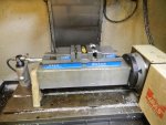
I draw it up just like a print with each face getting its own WCS. When I post, I go to each WCS change and add A0 and an appropriate clearance move.
When I set up, I probe the first WCS (usually G54) and run a macro that populates the rest of the WCS in that vise station.
Here's my 4th setup:
I draw it up just like a print with each face getting its own WCS. When I post, I go to each WCS change and add A0 and an appropriate clearance move.
When I set up, I probe the first WCS (usually G54) and run a macro that populates the rest of the WCS in that vise station.
Here's my 4th setup:
booze
I am too but really 1.5 man shop if you count the wife")
I tried the same set up, with manual double kurt vise unfortunately mine wouldnt clear 360 degrees with out hitting the side of vice jaw. I was using 4" square block for a trunion.
does that setup spin 360 degrees?
I am too but really 1.5 man shop if you count the wife
I tried the same set up, with manual double kurt vise unfortunately mine wouldnt clear 360 degrees with out hitting the side of vice jaw. I was using 4" square block for a trunion.
does that setup spin 360 degrees?
Riser block?booze
I am too but really 1.5 man shop if you count the wife
I tried the same set up, with manual double kurt vise unfortunately mine wouldnt clear 360 degrees with out hitting the side of vice jaw. I was using 4" square block for a trunion.
does that setup spin 360 degrees?
Done that a few times to swing some parts.
Not really relevant to this conversation, but I actually machined mounting points for the 4th into the edge of the table of our bridge mill, to swing a short, large diameter part, and that has proven useful a number of times since. It's a 320mm rotary, part was 850mm OD.
Booze Daily
Active member
No, it won't spin 360 with the vise. I don't run much prodution so I don't worry about loading it up like a tombstone.booze
I am too but really 1.5 man shop if you count the wife
I tried the same set up, with manual double kurt vise unfortunately mine wouldnt clear 360 degrees with out hitting the side of vice jaw. I was using 4" square block for a trunion.
does that setup spin 360 degrees?
I used to run a lot of medical parts and this allowed me to get at all kinds of angles for features and blending.
Mud
Well-known member
You can do something like this. this is on a machine I bought but don't have setup yet.booze
I am too but really 1.5 man shop if you count the wife
I tried the same set up, with manual double kurt vise unfortunately mine wouldnt clear 360 degrees with out hitting the side of vice jaw. I was using 4" square block for a trunion.
does that setup spin 360 degrees?
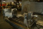
When we bought a trunnion unit for our biggest 4th, it actually came with a pair of nice fully ground plates that attach to the tables of the 4th and the trunnion, with a step to hold a sub-table on centreline.You can do something like this. this is on a machine I bought but don't have setup yet.
View attachment 145
I used spacer plates before on then 4th for some 12inch parts we had to do end work on.
I havent tried it on our trunion yet with the vises. matter of fact never even thought about it years ago with the vises. going to have to cad that up and see how much I need to raise that as it might work pretty good..
the one problem I have is I need the vise jaws to go length wise, as our parts are long and narrow. the thread were we were talking about it on pm got orange vise's interest in it and he made those little vises they were great but they were a tad too tall for me and I didnt like the jaws they used. I still need jaws 6-9" wide for out parts. just a super low profile
I had started to build my own vises into a 4.5x4.5 block then said screw it dont have the time. I should make the time to do it. theres nothing real hard about making a vise especially out of alum, decent screws are avail everywhere as well as the half balls that Kurt uses for pull down,
Mhajicek
Active member
Or use Mitee Byte clamps.
mitee byte clamps wont work in most of out applications, I do use them when I can.
our blanks are usually precision ground alum blanks thickness and outside dims are finished.
On a side note, Sorry I got this topic off topic. I got some pics of the set-ups I'm trying to create and some drawings. I'll dig them up sometime soon and put them in the fixture forum.
our blanks are usually precision ground alum blanks thickness and outside dims are finished.
On a side note, Sorry I got this topic off topic. I got some pics of the set-ups I'm trying to create and some drawings. I'll dig them up sometime soon and put them in the fixture forum.
I skimmed this thread so... any model that uses true threads is a waste of space/resources IMO. Delete them, or as said, model a dummy block to size. McMaster has a good resource of 3d files, and Harvey has great sim files (2d wf for Mastercam to create a tool ) to download.
Of course. That would give me what was needed for a WCS and to check clearances, and would take all of 20 seconds to add. Brilliant.model a dummy block to size
Mhajicek
Active member
I wouldn't say "any". In med device exactly how the threads begin and end, and interface with the features of the mating part can be a big deal, so we usually model them. We also do stupid things like a 10 degree tapered two start thread with a critical mating depth, or overlapping threaded holes at odd angles.I skimmed this thread so... any model that uses true threads is a waste of space/resources IMO. Delete them, or as said, model a dummy block to size. McMaster has a good resource of 3d files, and Harvey has great sim files (2d wf for Mastercam to create a tool ) to download.
I also kind of disagree with removing them as a matter of course. We do enough parts with timed/partial threads that they have to be modelled, but also it helps with programming blunt starts in a controlled manner (as in, no intervention at the machine to align them).I wouldn't say "any". In med device exactly how the threads begin and end, and interface with the features of the mating part can be a big deal, so we usually model them. We also do stupid things like a 10 degree tapered two start thread with a critical mating depth, or overlapping threaded holes at odd angles.
It doesn't hurt performance on any remotely recent hardware. I can't speak for mastercam though, I know it is a horrible resource hog, so maybe different for you because of that...
Mhajicek
Active member
Agree. I could see the argument a decade ago, but today we have enough horsepower its pretty much a non-issue. Mastercam user here.It doesn't hurt performance on any remotely recent hardware. I can't speak for mastercam though, I know it is a horrible resource hog, so maybe different for you because of that...