Mud
Well-known member
I thought he just didn't show up except as a blur?Bill, don’t you know that no camera can survive taking a pic of Garwood?

I thought he just didn't show up except as a blur?Bill, don’t you know that no camera can survive taking a pic of Garwood?
What's he saying to you? "Yep, I think its clear of the ground."Nope. I'm taking the picture. That's my good friend Nate looking like that because a minute before this picture he told me there's no way that forklift can lift that much. He sold me the forklift ,so he should know better.

I should have taken more pics of my businesses. Too busy working at the timeYou know, I never think about me being in pictures. I don't really have any with me in them. I think the only pictures of me are in my wifes phone and on her facebook page. I spose I should work on that? Someday when I'm long dead and my grandkids find a thumbdrive with thousands of pictures of machines and strange people with no context it won't make much sense will it? If I were in the pictures they might think I was something eh?

He was yelling "what the fuck are you doing jumping off that thing". I yelled back that I needed a picture to prove it did this.What's he saying to you? "Yep, I think its clear of the ground."
Very common of racers also. Too busy working to stop and take photos. There are almost no photos around taken by racers of long ago of themselves or their equipment, and it becomes an issue when someone is restoring or authenticating an old race car. Most get authenticated by photos in magazines., and that's only the most famous ones. The only photos I have from at the track were all taken by others, and almost none from at the shop. I did learn to take a photo of every car/motorcycle project before it left the shop the first time, in case it didn't make it back in one piece.I should have taken more pics of my businesses. Too busy working at the time
I would drill them out and install HD Keen-Serts if there is roomMight make some chips with this thing today.
I think Daewoo cut some corners with the turret and tool blocks on these machines. All my other lathes- Mori, Okuma, Leadwell, Mazak and even the lowly Hardinge have semi-hard turrets and hard toolblocks. Definitely not mild steel. They aren't soft.
This Puma's turret is not hard. All the 8mm threads are pulled from the turret. All of them. The PO tapped most of them out to 3/8"-16 and cobbled together some bullshit wedges that I didn't get with the machine.
All the ID tool blocks are cast steel or maybe nodular iron. They're soft as butter. The 2" bores are all worn oversize about 10 thou.
I can get running in the short term, but I can't live with the turret fucked all to hell limiting what tooling I put in which position.
I guess the first step is probably to pull the turret and see what's behind all existing stripped out holes. If I can drill and tap them all an additional inch deep and just run longer bolts then problem should be solved for awhile.
Other thoughts on thread repair for a turret?
Should I try sleeving the ID tool blocks or just make new ones?
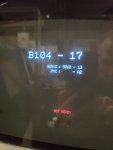
Hello Garwood,Is it possible for this machine to NOT have canned cycles? How do I tell?
I just drilled for the first time on this Puma. Had to remove G81 and finger cam it. Alarm said "Illegal G-code" at the G81 line.
Thanks Bill and Kevin!Hello Garwood,
The alarm number that resulted would have been a p/s010 alarm. If that is raised with any of the typical Canned Cycle "G" codes, that is evidence enough that the control does not have those cycles.
Unless the lathe has live tools, its not common for the control to have the Canned Cycles you're used to on a Machining Centre, such as G81, G82, etc. These are Options and seldom supplied unles specifically ordered.
What is more likely for your machine to have is G74, End Face Peck Drilling. The Canned Cycles you referred to with G81, use G80 (or any Group1 G Code) to cancel. The G74 Cycle is more like the other Milt-repetitive Cycles G71, G72, etc. and although G74 is listed by Fanuc as an End Face Peck Drilling Cycle, its actually an End Face Peck Grooving Cycle, where an End Coordinate in X and an amount of Step Over can be specified. The syntax for its use with controls that use the two line format for Milt-repetitive (Standard FS16 Format) is as follows
G74R (e) ;
G74X Z P(i) Q(k) R(d) F (f ) ;
Where:
X = X coordinate of the opposite side of the Groove from where you start the Groove in X
Z = Z coordinate of the bottom of the Groove.
e =Retract amount after each Peck
i = Step Over in X
k = Peck amount in Z
d = Relief from the wall of the Groove being cut at the completion of each cut down to the Z coordinate.
Care needs to be taken when specifying R(d), because on the first cut into solid metal there is nowhere for the tool to be able to step sideways
when at the bottom of the first cut. Accordingly, when cutting a groove into solid material, an initial Groove needs to be cut with no side relief R(d) value, then a second Grooving Cycle specified to widen the Groove and use R(d) with a value to relieve the tool from the side of the Groove on retract to start subsequent cuts.
f = Feed Rate
From the above, it should be obvious that by specifying the components of the Cycle with the same Finish X value as the Start X, no Step Over P(i) and no relief from the side of the Groove at the bottom of the Groove R(d), you can use it as a Peck Drilling Cycle. For example:
G00 X0.0 Z10.0
G01 Z1.0 F1.0
G74 R(e)
G74 X0.0 Z-50.0 Q5.0 F0.25 (The X address can be omitted for a drilling operation, or when the Groove is the same width as the tool)
Sorry Kevin. I didn't mean to steal your thunder regarding typical Canned Cycles found on machining Centres, not being supplied on lathes unless they have live tools; you Posted while I was typing my long winded reply.
Regards,
Bill
Hello Garwood,I'm learning a new CAM software and that's what it spit out. I will use G73/G74.

Thanks Bill - every day's a school day!Hello Barbter,
The G80 after the Cycle is not required; Its not that type of Canned Cycle, its part of the G70 – G76 Multi-repetitive Cycles, none of which require a cancellation code, they are all one off applications that come to and end on completion of the Cycle.
Regards,
Bill